Friday

Time passes.

 ~*~

 It is quite some time since I posted anything on my Pulsynetic blog. My wife died in 2022 after 55 years of marriage. This was followed by serious heart plumbing problems a couple of years later. This despite my fitness and lifelong walking and cycling. An ambulance ride or two with flashing blue lights and I was fitted with four stents in a bit of a hurry. 

 Both events destroyed all interest in what had been lifelong obsessions in multiple subjects. My interest in clocks goes back to my teenage years and I will be 80 years old in only a couple of months. 

 Electric clocks, as well as weight driven, were my passion for most of my life. I collected books and fewer clocks as funds allowed. I was extremely lucky and managed to find affordable examples of the main, British, master clocks. Even a Pulsynetic Waiting Train movement. 

 I was an early adopter of the internet when there was resistance from the usually elderly collectors. Forums and blogging allowed me to share my interests remotely but free of charge. I could add my own photos and share illustrations which I came across. It all seems so very long ago now. 

 Thirty years ago my wife and I moved to Denmark. Which distanced me from the UK's secondhand bookshops. Which I had scoured so avidly for literally decades. It placed me even further from casual discovery of interesting clocks for sale. My collection stagnated. So I blogged and posted on forums instead. It felt as if I was still connected to fellow collectors.

 Selling my clocks online is no doubt possible. Getting them to the buyers is far more difficult. These clocks are heavy, contain demolition weight pendulums and have glass fronts to their cases. A combination which precludes bubble wrap or a few polystyrene kidney beans for packing. I brought all my clocks over from the UK in the back of my car on the ferry. That ferry no longer exists!

 I mentioned that I wanted to downsize my collection on the clock forums. This produced no interest. My 60+ collection of books on clocks and electric clocks much the same. Having spent considerable sums on some of these books I was loathe to just dump them as waste paper. Or even to pass them onto somebody. Who would turn them to a profit entirely at my expense. The local charity shops certainly aren't interested. Nor the Danish, secondhand bookshops. All my books are in English and nobody reads books any more! Even international library charities weren't willing to accept a donation of my thousands of books.

 So the collection gathers dust and the books sit safely in boxes. Along with 25 other large, removal boxes. Which hold my lifetime library on countless other subjects. All non-fiction. Nobody here will have a clue what any of it is. Nor the remotest idea as to value. A Danish household item auction would hardly cover the cost of the fuel to get there.

 I inquired of an online app connecting returning lorry drivers in Europe with the UK . The cost of delivering a single master clock would greatly exceed its value in the UK. Perhaps I was just unlucky amongst the very small sample who responded?

 If anyone has any ideas of how to dispense with my clock or book collection I'd be very interested. If anyone wants to buy any of the clocks illustrated within my blog then do, please get in touch. The clocks can be seen working on my YouTube channel as "Tricyklist." Click on Videos and then Oldest. My early videos go back 18 years! With digital camera technology advancing rapidly over time. 

 Thank you for your interest if you have reached this far. It has been a very long but interesting journey for me. A lifetime obsession, if you will.

 Best regards

 Chris [Christopher] Bolwell

 chris.b (at) smilemail.dk

 SW Fyn, central Denmark. 

 13.03.2026 Update: My WT turret clock movement is now in the safe hands of a clock enthusiast in Germany.  


~*~


Wednesday

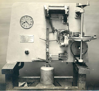
Cumbria Clock Co. Gillett & Johnston waiting train movement.

 *

 While image searching online for "waiting train clock" I came across a 2017 Cumbria Clock Co. Facebook discussion on the very rare Gillett & Johnston waiting train movement. 

 There was a superb B&W image. I have reproduced the largest version here: 960x862 pixels. For non-commercial, educational purposes. Click on the image for an enlargement.

Welcome to the Cumbria Clock Company - The Cumbria Clock Company

 The G&J movement is fascinating and beautifully constructed on a flat back plate. No doubt these movements were produced to order. In such small numbers that there was no need for investment in the main frame, cast iron moulds as used by Gents.

 Gillett & Johnston waiting train image original link:

 26047105_1575351909213434_8969796722705202208_n.jpg (JPEG Image, 960 × 862 pixels)

 I believe this is the fourth example of a G&J WT I have covered on my blog. This is by far the sharpest image of the mechanism so far.

 Here is the Ottawa G&J WT. Similar, but not the same. The Ottawa contact mechanism is much simpler.

https://waitingtrain.blogspot.com/2014/02/a-gillett-johnston-waiting-train.html 


*

Reproduction time setting dial for a WT C40A.

 *

An enterprising person has reproduced the C40A Time Setting dial for the waiting train movement. 

Made of silvered brass like the original. These time setting dials sometimes go missing when the lead-off work or bevel wheels are left in the clock room. Or scrapped through ignorance. 

The dial can be attached to a plain disk on the worm wheel shaft. There is no need for a bevel wheel cluster. Some WTs were fitted with only a time setting disk. Nothing more was needed when the WT was driving the hands of only a single dial. 

The time setting dial was vital for setting the time when the hands when the clocks changed. Or the WT [or clock] had been stopped for oiling or maintenance. The worm shaft of the WT was fitted with  small hand crank for advancing the clock hands. Note that the hands could not be turned backwards. One complete rotation of the time setting dial advanced the clock hands by one hour. So required advancing the hands by 11 hours to turn them back by one hour in the Autumn/Fall.

Available at £25 + postage on eBay[UK].

Gent Pulsynetic Waiting Train Turret Clock Time Setting Dial C40 or Similar | eBay


Tuesday

25.01.2022 DIY 6" Synchronome style, turret clock, slave movement.

 *

Many years ago I sawed out a 30" turret clock, skeleton dial. Which I laid over a matt black painted disk of the same size. I wanted to maintain high legibility. Fussy dials can rob the hands of clarity. Making reading the time unnecessarily difficult.

Then I made a 6" Ø ratchet wheel, slave dial movement to drive the counter-weighted, aluminium hands. I fitted the movement with double locking like other heavy duty slaves. 

The double locking can be overcome for manual hand setting. By pressing the armature up to the electromagnet cores. Though hand movement is only possible in a forward direction.

The 120 tooth ratchet wheel was cut with a slitting saw on my Smart & Brown 'Sabel' lathe. Using a large, home made dividing disk in polycarbonate. I scribed the divisions on the disk with dividers and then used a small center drill in the drill stand to ensure accuracy. A pin on a stiff, sprung blade located the drilled holes in the dividing disk on the tail end of the headstock. 

 The idea was to minimize errors of tooth pitch, by the ratio of dividing wheel diameter, to wheel, tooth pitch. I cut the reduction [motionwork] wheels my a similar method.

 The twin electromagnet coils were wound on my lathe in back gear. While I wore hide gloves to maintain tension. The cores and armature were of mild steel. Which had been repeatedly annealed in a wood stove. By leaving the stove to cool overnight. After soaking the metal in red heat for most of the day. The bed of ashes slowed the loss of heat in the metal components.

  Despite my patient efforts the mild steel still retained some residual magnetism. Which could have been overcome with an insulating layer over the cores. Copper shim material works well. I did not try this at the time and the clock hands would eventually stop. With the armature held firmly onto the faces of the cores despite heavy, coil spring, driving power. 

 A [clock] slave works by an electromagnet[s] pulling back a drive pawl on a lever. This occurs during a short electrical impulse from a master clock. So that one tooth of the ratchet wheel is gathered. Then, when the magnetic pull ends, a spring pushes the ratchet wheel forwards, via the drive pawl, by one tooth. The drive pawl and a backstop click prevent overrun and backward movement. Most British master clocks of the first quarter of the 20th century impulsed twice a minute. Requiring a 120 tooth ratchet wheel to drive the minute hand on the same shaft. The minute hand steps forwards in half minute jerks. The hour hand is mounted on a pipe surrounding the minute shaft. 

 Soon afterwards I was offered a genuine, Synchronome No4 slave movement with a 4" ratchet wheel. Due to the residual magnetism problem I immediately retired the bigger [home made] slave. The Synchronome movement has since been working for many years. With almost perfect reliability. Its Achilles heel being ice forming in the hour pipe. I increased the spring pressure and oiled the hour pipe. No further stoppages have occurred.  The original skeleton dial was replaced by a larger [secondhand] GRP dial 3' in diameter. This is easily legible from up to 200 yards away.


*


Wednesday

19.01.2022 Dimensions of the drive and WT coils.

 *

 I have been requested to supply the dimensions of the electromagnet coils of my C40A. This would be useful information if one needed to replace damaged or missing coils. Or even planned to build a replica of the WT. Which need not follow the original, mechanical design in other than the basic technique.

 Building a new WT main frame could be based on a heavy plate of steel or aluminium. Water jet or plasma cutting is available as a service. The WT's various components could be mounted on blocks. 

 Even multi-laminated Baltic birch plywood could be used to build up the WT's frame profile. Quite a useful material provided it was glued with a suitable adhesive. Epoxy perhaps?  

 While 3D printing offers an even better chance of matching the original appearance of a WT. Albeit with some considerable complication. Digital scanning of an original WT? Not an area with which I am familiar. 

 I have just checked back on my first posts from 2008. The large, pendulum drive coils have a combined resistance of 47 Ohms. These coils are driven by an independent 24V DC supply. NOT the intermittent timekeeping pulse.

 The much smaller, relay electromagnet [WT timekeeping release] has a resistance of 15Ω [Ohms.] Which is rather more than common wall dials. This will require the series time circuit, from the controlling master clock, is set to a current of 0.22 Amps. 

 Note that my coils have been wax coated over the silk wound wire. There is not much left of this protective wax after 80 years of cleaning. 

The earliest WT coils were "naked" wire silk wound. Wax coating lies somewhere in the middle to late 30s and early 40s. Followed by "bandaging" of the coils for even more protection.


Left Click on any image for an enlargement. Back click to return to the post.


*


Tuesday

Printed Pilot [time setting] dial and motionwork for the Gents' WT40A.

 *

 Following the images of the motionwork, in my last post, my contact has added a pilot dial.  The compact mechanism is driven by the WT exactly like the hands on a turret clock dial. The minute hand is directly driven by the bevel wheel cluster at 1 rph. The hour hand reduced to 1 revolution per 12 hour day. By the two pairs of spur gears with a ratio of 12.1. A typical, clock's motionwork. All thanks to precision, printed parts in bronze plastic.

The white dial even has the Gents' name for a further touch of authenticity. The raised numerals are a very nice touch. Reminiscent of Gent's very own exterior dials produced in massive cast iron. Though usually on a much larger scale than here. 

These dials were typically driven by a slave, impulse dial mechanism and intended for exposed positions. Or even to be sited where there was a risk of explosion from a spark. Such as an explosives factory. Or where the atmosphere has flammable gas or vapours present.

 This dial is small enough not to hide the features of the WT and certainly looks the part. Providing a time service as accurate as the master clock which controls the WT via the Gents' Waiting Train mechanism. Where, twice a minute, the drive to the clock hands is paused for about 2 seconds. A D-shaped pin, on the escape wheel, has lifted and locked the drive pawl, masking detent.
 
 Then the next, short, electrical impulse from the master clock reaches the WT's small, relay electromagnet at 30 second intervals. Allowing the drive pawl to drop back into the teeth of the WT's escape wheel as the masking detent drops. The hands move on without the pause being perceptible to the observer.

 I think you will agree that this pilot dial makes a compact, interesting and attractive feature. Moreover it allows more accurate setting of the WT to time. For example, when the clocks go back and forwards for summer and winter time. Or after a stop for maintenance or lubrication. 


 *


Friday

Printed clock hands and motionwork for WT C40A.

 * 


My contact with the C40A has kindly forwarded some images of his newly printed clock parts. 

He wanted to show the time on his WT. While the time setting dial can show the time [against suitable, fixed pointer] it does not have an hour hand. Much like most other turret clocks with time setting dials. So he printed clock hands, a bracket and the gearing [12:1] motionwork] to make the time more accessible.

The WT has an output of 1 revolution per hour. Or minute hand time. This has to be slowed by 12 times to drive an hour hand. One revolution per 12 hours. The compact, 3x & 4x spur gear,  reduction is known as motionwork. i.e. Producing the motion of the hour hand. The reduced speed is applied to an hour pipe. With the original minute hand on a shaft running inside the pipe. This is common to almost all of the mechanical clocks ever made. Including electrically driven clocks and slave dials.

My contact has cleverly printed a supporting bracket. This uses the original holes in the WT mainframe for fixing screws. 

One should never arbitrarily drill new holes in items of historical or antique value. Originality is highly admired and can make or ruin the resale value of items like clocks.  

The images show the details of the clever conversion to hour and minute hands. Provided there is low friction, the motionwork should not affect the working of the WT. The time cannot become wrong because of the enormous reserve of power available. More frequent impulsing of the pendulum is the usual sign of increased friction. This should be attended to immediately in order to avoid costly damage to irreplaceable parts.

Even the Gents' "Pulsynetic" brand name has been printed on the bracket. I doubt that anyone will be fooled into thinking this is an original WT part. Simply due to the materials used in the 3D printing.  Which is obviously intended as a fun exercise. Most owners of a WT and master clock would use the pilot dial in the master clock for timekeeping. Or place a slave dial nearby.

I use a Gents' slave dial on the wall above my WT. With a large, turret slave movement on the external dial. This avoids any risk to the WT. Which runs continuously but unloaded.


*

Thursday

18.11.2021 A WT C40A using 3D printing for missing parts.

 *

I have been contacted by a WT owner. Whom has cleverly 3D printed some missing parts.  

Of particular interest is his printing of a bevel gear, crown wheel. Even down to his use of the correct bronze colour. The bevel gears [or bevel wheels] sometimes seem to go missing when a WT is removed from an installation. Spares are rarer than unicorns these days.

 I think I also notice a couple of printed, universal-expansion joints for the lead-off work. Making the drive to large dials possible. 

 My contact has kindly forwarded some fine images of his WT. For which I am very grateful. I have reduced the size of the original images to cater for those on a slow internet connection. Any reduction in image quality is entirely my fault.

The overall impression of this WT is that it could have just left the factory. Despite being at least 70 years old. This WT has been beautifully restored and finished. Making for a superb, working, display item. The timber stand is very pleasing and a close match to originals I have seen online. The diagonal struts are useful in resisting the power impulse and should extend the period between mechanical impulses to drive the pendulum.

Certain details point to a later WT movement. It has the pressed steel, contact, steady bars. Rather than the earlier cast brass. Small parts are plated for protection. Rather than the earlier, deep-gold, lacquered brass. The sloping mainframe bar, over the power [pendulum drive] electromagnets, is indicative of a slightly later model of WT C40A. Probably 1940s-50s? 

Interestingly, the coils are silk wrapped wire. Which is the earliest winding arrangement of the huge coils by the Gents factory. Later, the coils were wrapped individually in a protective bandage. Intermediate coils were wax dipped to prevent moisture ingress.

This image shows the overall view from the rear of the WT movement. I used the terms "front" and "rear" because the time setting crank and dial were at the front. Not all WT movements were placed for easy access from both sides.


This image shows the similarity of the 3D printed, bevel, crown wheel to an original. One has to stare hard at it to see any difference. A truly remarkable feat using modern technology. Not to mention considerable skill and patience.

The bevel gear cluster is driven by the worm wheel shaft via the first, vertical, bevel wheel. The larger, horizontal, crown wheel drives all the other wheels. Allowing a drive for the hands of up to three dials. A fourth dial would require a coupling on the far end of the worm shaft.

Many towers would have a dial on each face. Each placing greater demands on the WT depending on wind speed and direction. Plus any ice forming on the very exposed, metal hands. The clock hands would normally be balanced just behind the dial. Using counterweights, on extended arms, jutting from the shafts. Ice would add considerably more weight to the hands. Causing the clock to work harder "uphill" as the hand rise and running ahead on the descent.


Another view of the bevel wheel cluster. A very satisfying appearance. I have zero knowledge about the strength of 3D printing materials. The WT can produce enormous torque when it is demanded. Which is why it is built to resist all the likely forces applied to the large, exposed, clock hands. Often on multiple dials over a long, working life and usually in less than ideal conditions.  

Many clock rooms, towers and roofs would suffer from wind blown dust, rain, snow and debris. Particularly if bells were employed behind open louvers. Birds would often carry twigs into buildings for nesting material. Proximity to the sea would carry corrosive salts in the air.

Many WTs would be protected by a simple wooden box placed over the movement. This protection would often be complicated by the lead-off rods. It relied heavily on the clock minder replacing the box after examining the WT movement. 


End view of the WT with the original "Pulsynetic" label on the sloping section of the mainframe.

The compact form of the WT, compared to weight driven clocks, is readily apparent. Not only that, but no weight shafts would be needed. Nor safe and easy access required for a clock winder and minder.

This allowed WTs to be placed in very unlikely positions compared with weight driven clocks. High up on narrow war memorials. In niches on factory chimneys. Inside illuminated dials on train stations. They were also employed to slowly drive display mechanisms, museum and exhibition items.

The worm shaft [arbor] rotated at 1 revolution per hour. Clock dials have a 12:1 "motion work" to drive the hour hands. A straight-through shaft would drive the minute hand inside the "hour pipe." The hour hand would be fixed onto the hour pipe.


The view from the opposite end. Where the terminal block is fixed. This has separate screw terminals for power and for timing pulses. The timing pulses arrive at 30 second intervals from a master clock in a series circuit including dials. The short pulse in the series circuit releases the temporarily locked "waiting train" mechanism. 

A small electromagnet is energized by the electrical pulse. Which releases an arm which was holding back the WT's drive to the clock hand[s]. The pause is usually so short [2 seconds] that the effect on the clock dial is never noticed. The drive to the clock hands is otherwise continuous. 

The huge, drive electromagnets require 20Volts DC and at least 0.5A. The pendulum uses a Hipp Toggle and V-block to call on a drive impulse if the swing [arc] drops below certain level. The impulse can be repeated as often as necessary to maintain the swing. Providing up to 30 times the power of the occasional impulse!

 Note the small hand crank jutting from the front of the WT movement.
This was used to set the WT's dial[s] to time.

Here the view is from the front of the movement showing the bevel wheel cluster seen through an aperture in the WT frame.

The Hipp toggle and damper lies just below. The damper prevents the Hipp toggle from catching in the V-block on the return journey of the pendulum. A stub of rubber hose on the tip of the arm silences any rattle. 

The original, time setting dial is present on the face of a bevel wheel. The hand crank would be turned on the WT worm shaft [arbor] to move the hands on the dials forwards. A pointer of bent brass sheet is usually present to indicate the time. 

The time setting dial having quarter hour markers. A valuable asset before the mobile phone could be used to tell the clock adjuster the time showing on the external dial[s.] A regular difficulty arising when the annual Spring and Autumn time adjustments take place for Summer and Winter Time. Also known as "Daylight Saving Time."    

A close-up of the lead off work on the end of the worm wheel shaft. [arbor in horological terms] This link would often provide the drive to a single dial. Or a further dials if a bevel gear cluster was present.  The printed expansion link is in the foreground. Yet to be trimmed to two bars to fit into the forked element just beyond.

This clever arrangement has been used for centuries in turret clock, lead-off work. The drive rods to the hands of distant dials, would expand and contract in roof spaces and towers with changing temperature. Soaring in summer and freezing in winter. The change in rod length could be accommodated by the slots ion the drive links.

Old buildings would settle and move over time. Requiring a degree of flexibility in the lead-off work. These reliable, low friction, bar and fork links provided the vital freedom in the [often] very long drive rods. The earlier links would probably be hand forged by a smith in red hot iron. 

The further advantage of a fork and bar, drive link was the inability of the drive rods to turn backwards. So that the time would not be lost due to any imbalance in the system. [Ice or wind on the hands] Nor vary much between widely separated dials on different parts of a building. Few architects would have the necessary funds to provide a separate WT for each dial on a building. Multiple WTs were usually reserved for the very largest dials in history. On prestige building projects at the beginning of the 20th Century. The Liver Building in Liverpool being an excellent example.

One weakness in the drive rod [lead off] system was corrosion in the plain bearings required to keep the rods on line. Weight driven, turret clocks usually had a much smaller safety margin against friction or wind pressure on the hands. The clock would stop. While the WT was uniquely powerful thanks to the automatically demanded multiples of drive impulses to the pendulum. All thanks to the genius of the Hipp Toggle system.

This might cause problems. If the power demand was simply to overcome friction in the lead-off work. Possibly even causing damage. Clambering about in a vast, draughty and unlit roof or tower. To check for bearing tightness in the lead-off work, can't have been an easy task. The WT would carry on regardless until something finally broke. This might explain the loss of bevel wheels. If the [bevel gear] teeth were the weakest point in the whole system.


*

Wednesday

23.12.2020 Gent's Bell-ringer Contacts.

*

I was asked, in the comments section, to share some images of the Gent's Bell-ringer contacts.  Bell-ringers were commonly used in schools to provide accurate and universal timing of classes.

The contacts vary in number, but my own, single circuit contacts are shown here. Multiple contacts were supplied, to order, by Gents. To allow individual bell ringing circuits. Perhaps for use in different areas of a building or complex.


Note that there are two distinct sets of contacts:

The lower set are situated left of the centre of the movement. They are actuated by a cam and offer weekend silencing. Or any other silencing period with a suitable cam. Slots in the day of the week wheel allows some adjustment by loosening the visible screws.

These contacts are normally CLOSED. If they are open then the bell system is silenced.


The second set of contacts are activated by tapered pins inserted into the 24 hour wheel. These contacts are found at upper left of the bell-ringer movement. Fitting pins in specific holes will allow a day and night choice of electric bells being rung as frequently as small fractions of any hour. These contacts are normally OPEN.   When a pin comes around it lifts the shaped, brass, contact actuator. The circuit is then closed until the pin moves on and releases the contacts again.   A tilting mercury switch limits the duration of the bell circuit to a few seconds to avoid tedium. A toggle switch is provided to silence the bells. While a push button is provided for alarms, drills, etc. Naturally the contact system can be used for other timing purposes.                                                                                      
WARNING! Be VERY careful in your choice of pins if you need more or lack any at all. I bought some large, standard, tapered clock pins and found them too long. Not having noticed this problem immediately, they completely locked up the bell-ringer movement. A pin had jammed against the frame. I had to clip off the shiny new pins to a safe length and then round the ends neatly over again. 
 
 
______________________________________
 
My apologies for the poor layout of this post. After years of practice, Google Blogger has finally and completely ruined the familiar editing and composition features of blogger. They caused this with an "update" aimed primarily at mobile phone users. I took the provided option to reject the change and continue with the original blog format. Only to find that I was now being punished for my recalcitrance. 
 
It is no longer possible to drag and drop images or text or even to expect auto justification of text around images. Hence the large gaps where text should normally exist! I have had to use "jump break" to keep the text in a relevant position beside the images. 
 
They ruined the HTML editing facility too. So it is no longer possible to undo the damage they cause in standard composition. WYSIWYG. Remember that these incompetents are largely in charge of the world these days. Though you are not provided with a vote to get rid of them.


*

Sunday

6.12.2020 Another WT on Ebay UK.

 *

Too unwell to spend hours processing images and writing detailed text for the blog.

Gents Pulsynetic Waiting Train Turret Clock .in Somerset | eBay

Probably WW2-1940s "marine" paint colour with the [earlier] matching "shoulders" to the cast main frame. What I like to think of as the "organic" frame style before they become more industrialised.

All plated parts, bandaged coils and pressed contact steadies suggest a slightly later model. Though not as late as the all grey, sloping shoulder type which followed.

It looks quite "tidy" but needs a careful clean and attention to fragile wiring details. It is missing its time setting crank on the front of the worm arbor/shaft. Fortunately, the time setting dial is presently hidden away at the rear. It would be better if more exposed. Somewhere on the end of the wormwheel shaft near the rather "unlikely" universal joint would do. Then it could be better seen for time setting. 

The ring type, universal joint, could be replaced with a more appropriate, forked, turret clock, expansion-universal joint. Thermal expansion of the lead-off work [to the often, distant dials] would put tremendous loads on the ends of long shaft unless they were suitable slotted. A practice applied for centuries to most turret clocks. The fork and pin drive will allow the vital freedom to expand and contract in unheated attics, lofts, roof spaces and clock rooms.

Making a new time setting crank, in keeping with the original, is a fairly trivial task. I made my own using a the crank from a vintage, domestic, pepper mill with a nicely worn wooden handle. A white, porcelain handle is more often seen and perhaps more original. A reproduction, porcelain, corded, light pull might suit this task.

No bevel gears and missing its Pendulum bob.  The latter is far more vital but reproducible from drawings, photographs and/or dimensions. Though it will not be original it can be faked if you have access to suiable materials and an original to copy. 

A variety of paint colours have been applied to WT bobs to bring attention to the swinging danger in confined spaces. White or even red paint has shown up in several online images. Others are painted the same colour as the frame left the factory. 

One has to take great care when adjusting a working WT movement to avoid trapped fingers. The inertia of the heavy pendulum and rapid movement of the armature can catch the unwary owner out.

 Watching a WT in action is hypnotising as the Hipp toggle and waiting train mechanism take turns for one's attention. I have mine on a sturdy shelf with hefty, cast shelf brackets. So I can watch it at eye level whenever I am passing by.

There is no need for a WT to be very noisy. Though they were never meant for such use they can be domesticated by careful adjustment and damping the armature's range stops with rubber. A solid bench or stand is desirable to avoid rocking and to avoid amplifying any noise. 

I never got around to building the "trestle" style stand, in oak, which was sometimes provided by the Gents factory. Many WTs stood on wooden benches. With a generous slot cut for the pendulum rod to allow the large bob to swing freely underneath. Too short a slot will soon find the limits of swing demanded by an active WT. Better too long a slot than too short.

This fine WT reached £1272 on eBay[UK] despite the lack of a pendulum. We hope the winner completes the movement to their own satisfaction and enjoys their ownership. 


*

Tuesday

Waiting train pendulum impulse in Slow Motion.

*

The pendulum impulsing of the Waiting Train happens too fast to be sure what is happening. 

So I recorded a video at 150fps to display the impulsing action clearly as it is replayed in slow motion

The Hipp toggle closes the main contacts as the pendulum arc drops below the trigger point. The huge electromagnets are energised. Lifting the rocking armature with its impulsing roller. The upward pressure is maintained as the roller runs along dead face and then around the corner of the pallet. The Hipp toggle can be clearly seen in its action in the V-block before and during the impulse.


I have a piece of tough material trapped between the electromagnet cores and the armature to reduce the noise. There was once a rubber tap washer beneath the domed adjustment screw head but it has been lost or worn away. I fitted these to stop the loud clonk as the heavy armature lifted and dropped back against the cast main frame before and after the impulse.


 *

Saturday

A G&J motor driven striking unit on eBay.

*

Not much of interest on eBay lately. So it was pleasant to have something really interesting to share: A motor driven Gillett & Johnston striking unit.


Seller's eBay text:

"Gillett & Johnston electric striking unit with solenoid activated mercury tube switching. 1926 can be seen on the motor plate however I’m not sure if this is a date or not. If it is, then it’s very early however, I think it could be later than this.
 

I have connected the motor. Which runs but smokes badly. This could be from long term storage, deteriorating wiring or just old age. For clarity it being sold as not working. Please assume the motor will need repairing or replacing. The gearbox casing is completely non-ferrous – I assume gun metal so could polish up well.
 

It’s heavy – just over 40 kg so collection only unless you want to arrange a pallet. Overall measurements are 700 x 250 x 350 high.
 

Could be an interesting project for someone. Cash on collection please- not accepting PayPal for this."

 As can be seen and according to the seller's description some work will be involved in its restoration. Some considerable knowledge of electrical work will obviously be required for safety if it is intended to get it going again. Rather than as a static display.

 Motor rewinds are possible if the original motor casing is to be used. One hopes it can still meet modern levels of safety and reliability. It would be a shame to lose originality by fitting a modern motor. Old motors have their own unique style and personality.

These units were probably never intended to be seen by the general public. Though that did not stop these world famous, bell and clock manufacturers from producing a most attractive unit. One presumes that the drum-like casing, on top, houses a large, worm gear, speed reduction gearbox. Designed to turn the striking components at an acceptable striking speed with enough torque to lift a heavy bell hammer.

The spaced pins on the large, ratchet wheel ensure the correct number of blows are struck on each hour in turn. Far more useful and interesting, than a single strike on the hour. IMO. An advance lever is operated by a round cam on the outer end of the wormwheel shaft.

The mercury switch, to start the motor run, will be triggered by a master clock and its associated "bell ringer" unit. The latter were often to be found in schools to ring electric bells for timing classes. These "bell ringers" can still be found quite regularly on eBay and make most attractive, collector's items in a master clock system or collection.

I have resized the original auction images for the blog format. Left Click for enlargements.

Copied and shared for educational purposes. To extend the life of the seller's excellent images [and relevant information] beyond the close of the eBay auction. Good luck with your bidding!

This item sold for £146.67 GBP after 16 bids.

*

Monday

A clean, early example of the Gent's Pulsynetic C40A WT for sale.

*

For those who value originality and an early movement, in remarkable condition and good working order, there is a WT for sale at The Time Workshops: 


This electric, turret clock movement is remarkably complete. All the screws look original and in keeping with the mechanism. The main drive electromagnet coils are also early and of original appearance.

The minor components are all gold lacquered brass or bronze. All look original and match the early, black painted , mainframe period. Probably from around the time of the First World War. Or, about 100 years old. A true antique.

A single drive shaft leads off to the left of the movement with an extended bracket for support. A timekeeping dial is present behind the movement with a brass indicator.

The early form of cast, angular contact steady bars is present. Mounted on an original oval, horizontal support pillar.

The pendulum drive armature is of the early, solid type. Later examples had a roller. 

 This is a close up of the waiting train mechanism which controls the timekeeping of the turret, motor pendulum. A Pulsynetic master clock or impulse circuit will be required for a suitable dial and hands to keep good time. Without the brief, half minute impulse, the WT will run fast since it will not be paused as the designer's intended.

An authentic time setting crank is present. Useful for resetting the turret dial to time after a change to summer or winter time.,
The main contact assembly uses the Hipp Toggle and V-block to maintain the swing of pendulum regardless of resistance from the exposed clock hands. 

The genius of the design is that up to 30 times the normal power is available [completely automatically] on demand, to drive large clock hands on a suitable dial. Note the brass toggle damper on the right.

The original pendulum bob is a weighty affair in keeping with a turret clock. 


Please contact The Time Workshop for further details. 
A direct link appears at the top of this page.


Click on any image for an enlargement.
*

Friday

Curing erratic losing of a turret slave.

*

My Synchronome No4, turret slave movement had been losing erratically over this last winter. I had [incorrectly] put this down to frosts locking up the hour minute arbor in the hour barrel. Losing of random minutes always seemed to occur after an overnight frost despite adding oil.

Eventually I was forced to remove the hands. To allow me to take down the movement for examination and lubrication. All seemed to be well but with occasional failure to advance as I manually depressed the armature on the double electromagnets "right around the dial".  Or a complete rotation.

So I simply increased the tension on the spring blade slightly via the adjustment screw provided. Then refitted the movement and hands to the 30" dial. It hasn't lost any time ever since. It should be remembered that the minute hand is advanced in half minute steps. So failures soon add up and are, of course, cumulative. There is nothing worse than a clock which is showing the wrong time. Particularly a public clock dial. Fortunately, in my case, the clock is completely invisible. Except to occasional visitors like the postperson and ourselves.

The dial itself is moulded GRP, with gilded numerals and bought secondhand from the UK. I wanted a "well worn" appearance to suggest the dial was far more elderly than reality. This "tired" dial suited my needs to perfection. I am not a fan of newly gilded dials and actually dislike them. Since the restoration completely robs the dial and its associated clock of the unique character of [timeless] age.

I made the bare aluminium hands for a slightly larger skeleton dial which I had laboriously cut out myself. It is usual for the minute hand to extend over the numerals and well out to the minute markers or even beyond. They suit their purpose and are easily read in all light conditions thanks to the contrast against the black dial. It is all too common to see public dials which completely defeat their purpose due to unwanted ornamentation or poor contrast. Only the hands need be seen to read the time instantly and correctly. Decoration reduces this ability to foolish levels of complete illegibility.  


Click on any image for an enlargement.

*

Tuesday

Another G&J WT!

*

Thanks to a tip from a new contact I have discovered some excellent images of  the G&J WT installation at Bournville School in Birmingham. The clock and striking gear are part of the carillon. Which is a hand struck, mechanical lever and wire system for playing bells.

The Bournville carillon is well featured on YouTube. Here are only a couple of examples.

 https://youtu.be/0yzleb5McCw

 https://youtu.be/Mw_Uio_SedM
 
Sadly I have not found any videos of the clock system so far. Here are my sources for the excellent illustrations from a newspaper article on the Bournville clock system and carillon. There is even a website for the Carillon.


This is the third G&J Waiting Train movement which I have illustrated on my blog and all are completely different from each other. Suggesting, perhaps, that each new commission was treated as an individual project based on G&J's long expertise with clocks and bells.

The spotless living conditions for the movement and striking/chiming work are obvious. Keeping maintenance through wear and tear to a minimum. All too many turret clocks and bell tolling mechanisms live in absolute squalor.

The glass case keeps curious fingers and dirt well away from the WT [Waiting Train] movement.  It utilizes the familiar Hipp toggle and V-block pendulum maintenance. With its ability to draw more driving power simply by shortening the period between pendulum impulses.

In this case the pendulum is driven from below the bob by a pair of electromagnets. Their considerable offset means that the pendulum is driven at near the extremes of its swing.[arc] Thus any energy applied at this point has maximum effect. This impulse timing is normally avoided with precision clocks but the WT is immune to timekeeping errors. Since it is always under the control of an associated, precision, master clock.

Interestingly, there is a small mercury switch to the left of what I had first assumed to be the the Hipp contacts. Perhaps the mercury switch provides the contact when tipped by the Hipp toggle mechanism?

The rest of the WT mechanism is typically [visually] complex, for G&J,  and full of hidden mysteries. I am guessing that the train of three round objects on the right is tied to the electrical release of the chimes and hourly strike. The top wheel is marked in hours. While the second wheel has four studs. Suggesting chiming of the quarters?

No electrical wiring is directly associated with the "quarters" wheel. Though there are several levers which could be actuated by the four studs on the face [and possibly the rear] of this wheel.

While the lowest circular device is clearly wired and carries a mercury switch. The oblique view helps to show much more detail not visible in the "straight on" image. Three brass levers [or contact bars] on the rim of the lower wheel pointing upwards at the central "quarters" wheel. I would suggest that the lower wheel rocks rather than rotates.

The pendulum drives a ratchet wheel via a ramp and counterbalanced, actuating lever near the top. The ratchet wheel drives a worm which, in turn, drives a complex bevel gear system to the three wheels below, on the right.

There is a strong suggestion of a differential, bevel gear system being involved at the top right of the pendulum. Why else have two bevel gears facing each other on either side of the inner bevel wheel?

Striking is typically managed by an electric motor driving a large, snail cam to lift and drop a lever. This part of the mechanism is arranged on the left of the chiming gear nearest the WT movement. Though only electrical contact is required between the two.

There appears to be count wheel striking, with an associated, large ratchet wheel on the left of snail cam. So the number of blows [hours] of the strike is controlled by the count wheel. Just as it does in many common, 30-hour, long case clocks and others. There is a very long history of countwheel striking on turret clocks. 

The obviously high quality, chiming mechanism is rather like an overgrown music box in action. Except that the usual musical 'comb' is replaced by sturdy levers leading to actuating cables to each overhead bell. The timing of the individual bells can be individually adjusted [if necessary] by moving the let-off studs around the drum. Handy, should the studs wear over a long period. Which would alter the exact timing of lift and release. Making the timing of the "tune" sound slightly wrong.

I am indebted to the newspaper article linked to above for their excellent coverage and useful illustrations. It is well worth following the link to learn much more:

Hidden Spaces: Bournville Carillon - Birmingham Live


Click on any image for an enlargement.
*

Monday

Gents C40A WT in Yangon, Burma.

*

I was recently contacted by an international traveller who was curious about a clock movement he saw on a visit to Burma. I was even sent an image and then more later, to help to identify the movement. 

It is of course the partial remains of a later, Gent's C40A waiting train, turret clock.

Sadly the main, drive electromagnets are missing. 

The WT is situated at the Secretariat Building in Yangon. A superb building as can be seen in the background to the WT. 

The WT rests on a typical and sturdy, Gents style, clock table or bench. Which is well reinforced against rocking by triangulating, timber braces.

The pendulum still hangs patiently below the movement.

 While the Gents' name plate and hand setting dial are also still present.

The WT movement must be sheltered from direct rainfall or it would be in considerably worse condition by now.

My contact was told that there were a couple of slave dials involved but no mention, so far, of the vital, Pulsynetic master clock.

The view from the other side showing a later, grey painted model of the Gents waiting train. The sloping main frame above the [missing] electromagnets is a clear indicator of a later movement. I am guessing at late 1940s-50s? Though I have no real data on this matter.

I have no idea what appears on the large label dangling from the movement. Perhaps it refers to the whereabouts of the missing coils?

 The impressive and colourful Secretariat Building in Yangon as seen by Google Earth.


Click on any image for an enlargement.
*

Sunday

Later, step-framed, WT movements.

*

Later C40B & C40C WT movements took on a stepped mainframe design. The movement was compact and provided a clear area for the crown wheel and bevel gears. One might say they were "industrialized" in comparison with the earlier, "organic" main frame designs. 

The factory drawing alongside clearly states that this is a C40B. I don't yet have a drawing of a C40C to share here.


 And the physical reality: A C40B stepped frame WT. Expansion couplings are provided for at least three dials. Left, right and forwards. Another may face backwards out of sight.

There has been some reinforcement and simplification over the earlier curved frame models. Plated components are the norm to avoid corrosion.

The gathering pallet is now doubled to provide a straight draw on the ratchet [escape] wheel. 

The contact steady bars are of the later, pressed variety.

A near identical, step framed, C40B courtesy of Simon Boyd.

The typical drive to the lead-off work is clearly visible on the left. A crossbar is driven by a slotted channel to provide a positive, non-slip drive to the distant clock hands. While simultaneously allowing for thermal expansion and building movement.


 Another step-frame C40B in clean condition.

Pressed steel contact steady bars. All plated components.

This fine example was described as a C40C by the vendor. I called it a C40B and the mainframe shows B1 in the central casting. I must admit that I cannot identify any obvious differences from the C40B above.

The movement had been domesticated. By being installed into a fine, furniture quality, display cabinet.

The clock dial is unusual. Most WTs, with a forward facing bevel wheel, would have a time setting dial with mention of name and patents. Perhaps the domestication required a readable time indication? If so, it was tastefully done.


An almost perfectly matching step-framed WT from Clock.doc. C40B? Or 40C?

 WT R 1.jpg (JPEG Image, 640 × 609 pixels)

Perhaps it is merely a matter of scale? The C40B at the top of the page has a perforated crown wheel. Both of these  C40Cs have a solid crown wheel to the bevel wheel cluster. The black paint is usually considered as a sign of an early movement.Yet both "C" movement have later plated components and pressed, contact steady bars.


Click on any image for an enlargement.
*