Wednesday

Cumbria Clock Co. Gillett & Johnston waiting train movement.

 *

 While image searching online for "waiting train clock" I came across a 2017 Cumbria Clock Co. Facebook discussion on the very rare Gillett & Johnston waiting train movement. 

 There was a superb B&W image. I have reproduced the largest version here: 960x862 pixels. For non-commercial, educational purposes. Click on the image for an enlargement.

Welcome to the Cumbria Clock Company - The Cumbria Clock Company

 The G&J movement is fascinating and beautifully constructed on a flat back plate. No doubt these movements were produced to order. In such small numbers that there was no need for investment in the main frame, cast iron moulds as used by Gents.

 Gillett & Johnston waiting train image original link:

 26047105_1575351909213434_8969796722705202208_n.jpg (JPEG Image, 960 × 862 pixels)

 I believe this is the fourth example of a G&J WT I have covered on my blog. This is by far the sharpest image of the mechanism so far.

 Here is the Ottawa G&J WT. Similar, but not the same. The Ottawa contact mechanism is much simpler.

https://waitingtrain.blogspot.com/2014/02/a-gillett-johnston-waiting-train.html 


*

Reproduction time setting dial for a WT C40A.

 *

An enterprising person has reproduced the C40A Time Setting dial for the waiting train movement. 

Made of silvered brass like the original. These time setting dials sometimes go missing when the lead-off work or bevel wheels are left in the clock room. Or scrapped through ignorance. 

The dial can be attached to a plain disk on the worm wheel shaft. There is no need for a bevel wheel cluster. Some WTs were fitted with only a time setting disk. Nothing more was needed when the WT was driving the hands of only a single dial. 

The time setting dial was vital for setting the time when the hands when the clocks changed. Or the WT [or clock] had been stopped for oiling or maintenance. The worm shaft of the WT was fitted with  small hand crank for advancing the clock hands. Note that the hands could not be turned backwards. One complete rotation of the time setting dial advanced the clock hands by one hour. So required advancing the hands by 11 hours to turn them back by one hour in the Autumn/Fall.

Available at £25 + postage on eBay[UK].

Gent Pulsynetic Waiting Train Turret Clock Time Setting Dial C40 or Similar | eBay


Tuesday

25.01.2022 DIY 6" Synchronome style, turret clock, slave movement.

 *

Many years ago I sawed out a 30" turret clock, skeleton dial. Which I laid over a matt black painted disk of the same size. I wanted to maintain high legibility. Fussy dials can rob the hands of clarity. Making reading the time unnecessarily difficult.

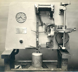
Then I made a 6" Ø ratchet wheel, slave dial movement to drive the counter-weighted, aluminium hands. I fitted the movement with double locking like other heavy duty slaves. 

The double locking can be overcome for manual hand setting. By pressing the armature up to the electromagnet cores. Though hand movement is only possible in a forward direction.

The 120 tooth ratchet wheel was cut with a slitting saw on my Smart & Brown 'Sabel' lathe. Using a large, home made dividing disk in polycarbonate. I scribed the divisions on the disk with dividers and then used a small center drill in the drill stand to ensure accuracy. A pin on a stiff, sprung blade located the drilled holes in the dividing disk on the tail end of the headstock. 

 The idea was to minimize errors of tooth pitch, by the ratio of dividing wheel diameter, to wheel, tooth pitch. I cut the reduction [motionwork] wheels my a similar method.

 The twin electromagnet coils were wound on my lathe in back gear. While I wore hide gloves to maintain tension. The cores and armature were of mild steel. Which had been repeatedly annealed in a wood stove. By leaving the stove to cool overnight. After soaking the metal in red heat for most of the day. The bed of ashes slowed the loss of heat in the metal components.

  Despite my patient efforts the mild steel still retained some residual magnetism. Which could have been overcome with an insulating layer over the cores. Copper shim material works well. I did not try this at the time and the clock hands would eventually stop. With the armature held firmly onto the faces of the cores despite heavy, coil spring, driving power. 

 A [clock] slave works by an electromagnet[s] pulling back a drive pawl on a lever. This occurs during a short electrical impulse from a master clock. So that one tooth of the ratchet wheel is gathered. Then, when the magnetic pull ends, a spring pushes the ratchet wheel forwards, via the drive pawl, by one tooth. The drive pawl and a backstop click prevent overrun and backward movement. Most British master clocks of the first quarter of the 20th century impulsed twice a minute. Requiring a 120 tooth ratchet wheel to drive the minute hand on the same shaft. The minute hand steps forwards in half minute jerks. The hour hand is mounted on a pipe surrounding the minute shaft. 

 Soon afterwards I was offered a genuine, Synchronome No4 slave movement with a 4" ratchet wheel. Due to the residual magnetism problem I immediately retired the bigger [home made] slave. The Synchronome movement has since been working for many years. With almost perfect reliability. Its Achilles heel being ice forming in the hour pipe. I increased the spring pressure and oiled the hour pipe. No further stoppages have occurred.  The original skeleton dial was replaced by a larger [secondhand] GRP dial 3' in diameter. This is easily legible from up to 200 yards away.


*


Wednesday

19.01.2022 Dimensions of the drive and WT coils.

 *

 I have been requested to supply the dimensions of the electromagnet coils of my C40A. This would be useful information if one needed to replace damaged or missing coils. Or even planned to build a replica of the WT. Which need not follow the original, mechanical design in other than the basic technique.

 Building a new WT main frame could be based on a heavy plate of steel or aluminium. Water jet or plasma cutting is available as a service. The WT's various components could be mounted on blocks. 

 Even multi-laminated Baltic birch plywood could be used to build up the WT's frame profile. Quite a useful material provided it was glued with a suitable adhesive. Epoxy perhaps?  

 While 3D printing offers an even better chance of matching the original appearance of a WT. Albeit with some considerable complication. Digital scanning of an original WT? Not an area with which I am familiar. 

 I have just checked back on my first posts from 2008. The large, pendulum drive coils have a combined resistance of 47 Ohms. These coils are driven by an independent 24V DC supply. NOT the intermittent timekeeping pulse.

 The much smaller, relay electromagnet [WT timekeeping release] has a resistance of 15Ω [Ohms.] Which is rather more than common wall dials. This will require the series time circuit, from the controlling master clock, is set to a current of 0.22 Amps. 

 Note that my coils have been wax coated over the silk wound wire. There is not much left of this protective wax after 80 years of cleaning. 

The earliest WT coils were "naked" wire silk wound. Wax coating lies somewhere in the middle to late 30s and early 40s. Followed by "bandaging" of the coils for even more protection.


Left Click on any image for an enlargement. Back click to return to the post.


*