*
There was a superb B&W image. I have reproduced the largest version here: 960x862 pixels. For non-commercial, educational purposes. Click on the image for an enlargement.
Welcome to the Cumbria Clock Company - The Cumbria Clock Company
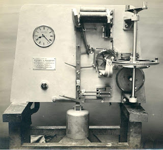
The G&J movement is fascinating and beautifully constructed on a flat back plate. No doubt these movements were produced to order. In such small numbers that there was no need for investment in the main frame, cast iron moulds as used by Gents.
Gillett & Johnston waiting train image original link:
26047105_1575351909213434_8969796722705202208_n.jpg (JPEG Image, 960 × 862 pixels)
I believe this is the fourth example of a G&J WT I have covered on my blog. This is by far the sharpest image of the mechanism so far.
Here is the Ottawa G&J WT. Similar, but not the same. The Ottawa contact mechanism is much simpler.
https://waitingtrain.blogspot.com/2014/02/a-gillett-johnston-waiting-train.html
*